Abstract – This article presents a report on the Components, Scientific theory, procedure and Precautions required to be taken for assembling an Arduino-based quadcopter. The main principle behind the flight of a quadcopter is Newton’s Third Law of motion, which states that for every action there’s an equal and opposite reaction. The scientific explanation of different components of the quadcopter have been given in details in the article.
Keywords – Arduino, Propellers, Transmitters, Batteries, Flight controller
Introduction
A drone is a generic term that refers to any kind of unmanned vehicle that doesn’t have a pilot or a driver. A drone can be any vehicle that moves in air, water, and on land. A quadcopter is a more defined word that refers to a drone that can fly using four rotors. In this project a quadcopter based on Arduino Uno R3 based was built, programmed and tested successfully.
Components
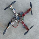
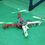
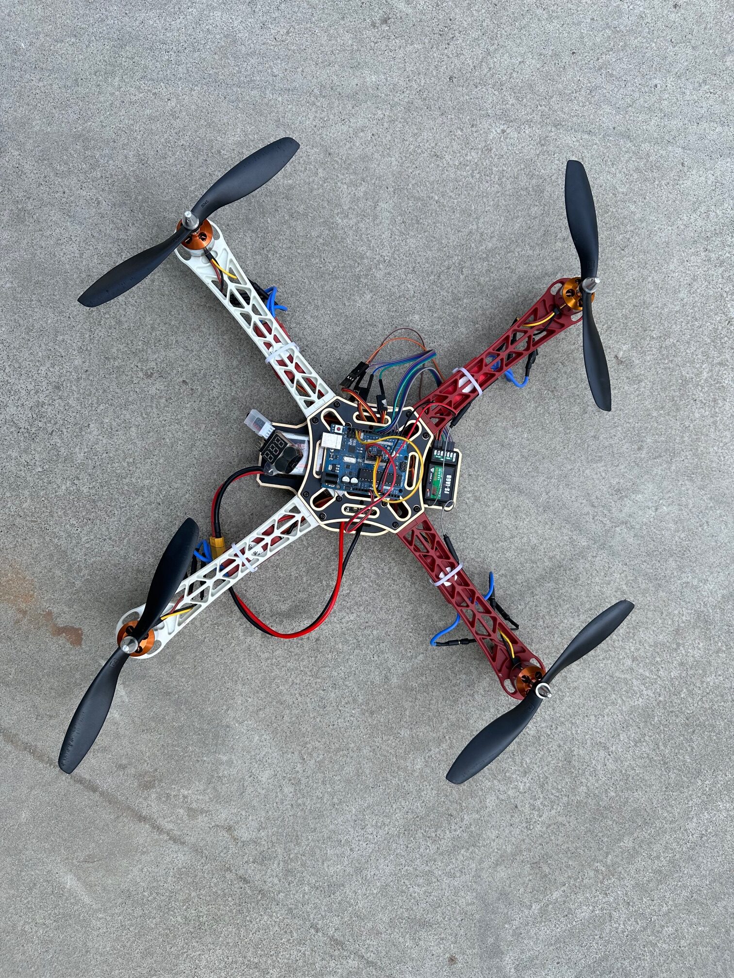
Carbon fiber frame
A quadcopter frame acts as skeleton of the entire machine. It should be light so that it can be lifted easily but should also be strong enough to hold the Arduino board, 4 BLDC motors with propellers, 4 ESCs, a LIPO battery and a receiver. We can build our own frames using aluminum, wood channels, plastic pipes, or we can buy readymade frames depending on the requirements.
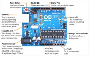
Arduino Uno R3 microcontroller:
Arduino board is the brain of the project. Arduino is an open-source microcontroller platform based on a simple input/output (I/O) board and a development environment that implements the Processing language. Arduino can be used to create interactive standalone objects or connect to software on computer. The Arduino platform can be used for sensing both digital and analog input signals and for sending digital and analog output signals to control devices.
MPU 6050 Gyroscope and Accelerometer
The MPU6050 is a Micro-Electro-Mechanical System(MEMS) that consists of a 3-axis Accelerometer and 3-axis Gyroscope inside it. This helps to measure acceleration, velocity, orientation, displacement and many other motion related parameters of the drone in all the X, Y and the Z-axis. When the sensor is rotated along any axis, the Coriolis Effect causes a vibration. The MEMS inside the MPU-6050 detects this vibration. The resulting signal is then amplified, demodulated, and filtered to produce a voltage that is proportional to the angular velocity.
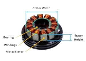
BLDC Motors:
BLDC motors stands for Brush Less Direct Current motors. There are 2 main types of BLDC motors: Inrunners and Outrunners. Outrunners are used for this project.
Benefits over brushed motors:
- High torque to weight ratio
- More torque per watt (increased efficiency)
- Less noise and longer life
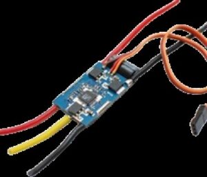
ESC’s
Every motor in Quadcopter requires an individual Electronic Speed Controller (ESC) which accepts commands from the Uno board in the form of Pulse Width Modulation (PWM) signals and control motor speeds accordingly. Every ESC has a current rating, which indicated the maximum current that it may provide to the motor without overheating.
PWM is a commonly used control technique that generates analog signals from digital devices such as microcontrollers.
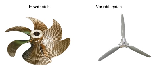
Propellers
The spinning blades of the propellers create a difference in air pressure, with air pressure being lower on below the blade than on top. The difference in the air pressure generates thrust, which lifts drone.
FS i6 transmitter
A Drone Radio Transmitter is an electronic device that uses radio signals to transmit commands wirelessly via a set radio frequency over to the Radio Receiver, which is connected to the drone being remotely controlled.
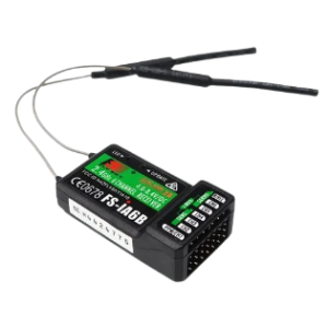
A Drone Radio Transmitter commonly uses the following frequencies: 27MHz, 72MHz, 433MHz, 900MHz, 1.3GHz, and 2.4 GHz.
Batteries :
Batteries can be broadly classified into two types: (a) Primary (b) Secondary
- Primary Batteries: Alkaline batteries, Aluminium air batteries, Dry cells
- Secondary Batteries: Li-Ion Batteries, Li-Po Batteries, Ni-MH Batteries. Lead-acid Batteries
Scientific theory:
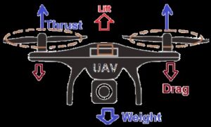
The main principle behind the flight of a quadcopter is Newton’s Third Law of motion, which states that for every action there’s an equal and opposite reaction. A quadcopter’s propellers push air downwards. This causes an opposite reaction called thrust that pushes the quadcopter upwards against gravity. Air movement comes from Bernoulli’s Principle, with larger propeller blades and faster rotation creating more thrust.
Bernoulli’s principle, formulated by Daniel Bernoulli, implies that as the speed of the wind increases, the pressure difference between the top and bottom of an airfoil increases.
When the propellers rotate clockwise, the quadcopter will tend to rotate anti-clockwise. Rotational force is called torque. Quadcopters solve this by driving two diagonal propellers clockwise and the other two anti-clockwise. Thus, torque from one pair cancels that of the other.
When each diagonal pair of propellers rotate in opposite directions, their thrusts will be in opposite directions. The quadcopter will not be able to lift up or fly. This is solved by having the blades of each diagonal pair of propellers shaped as mirror images of the other pair. Effectively, all propellers will push air downwards regardless of the direction of rotation.
Flight control is provided by the independent variation of speed and hence lift and torque of each motor. Thrust to weight ratio and KV rating are two primary factors in deciding the required motors.
How to Assemble:
Step 1: Pre-tin positive and negative nodes on F450 frame’s printed power distribution board
Step 2: Solder 4 ESCs to power board of F450 frame. Always connect red color from ESC to positive and black color to negative on power distribution board
Step 3: Solder XT60 connect to power distribution board
Step 4: Fix printed power board to frame arms, with white arms in the front and red in the back
Step 5: Fix BLDC motors in the designated slots at the end of each arm of the F450 frame, using M3 screws
Step 6: Connect all three nodes of BLDCs with respective ESCs.
Step 7: Check the direction of BLDC motor rotation, to change the direction of any motor we can inter change any two nodes
Step 8: Fix all wires and ESCs with quadcopter arms using cable ties
Building Flight Controller:
Step 9: Fix MPU6050 on the center of Arduino board, without touching any pins on the board, to avoid short circuit
Step 10: Fix Arduino board to F450 frame using double sided tape
Step 11: Connect VCC, GND, SCL and SDA pins on MPU 6050 with respective pins on Arduino board (Schematic Diagram available below)
Step 12: Connect jumper wires to all signal wires (Orange) of all 4 ESCs
Step 13: Connect the other end of these jumper wires to Arduino’s 4 to 7 pins
Step 14: Connect 5V and GND pins of 1st ESC to Receiver’s 5V and GND pins using jumper wires
Step 15: Take out 5V supply from receiver and connect with Arduino’s 5V supply, similarly 5V from Arduino will go to MPU6050
Step 16: Connect 1 to 4 signal pins on receiver with 8 to 11 pins on Arduino board
Programming:
Step 17: Calibrate all ESCs separately
Step 18: Download program code to Arduino app and complete setting up roll, pitch and yaw
Step 19: Apply the flight controller
ESC functional diagram
Circuit Diagram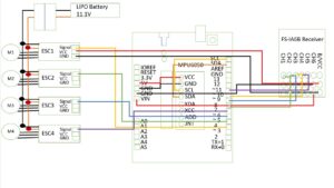
Care and Precaution
1. ESCs should be soldered to correct leads to avoid short circuit
2. The transmitter and receiver should be bound before programming.
3. 8” propellers must be used instead 10” for better stability
4. The gyro must be flat before calibration and should be calibrated precisely
5. The direction of BLDCs and the orientation of propellers must be correct
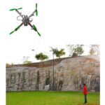
Output
Assembling and programming of Arduino Uno based quadcopter was completed. Also, the quadcopter was successfully tested for take-off, landing, forward- and backward movements.